Serial Communication
Before proceeding to further discussion on serial communication, let's take a brief intro for the parallel communication.
Parallel vs. Serial
Parallel interfaces transfer multiple bits at the same time. They usually require buses of data - transmitting across eight, sixteen, or more wires. Data is transferred in huge, crashing waves of 1’s and 0’s.
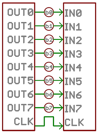
An 8-bit data bus, controlled by a clock, transmitting a byte every clock pulse. 9 wires are used.
Serial interfaces stream their data, one single bit at a time. These
interfaces can operate on as little as one wire, usually never more than
four.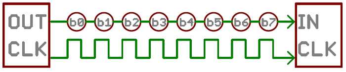
Parallel communication certainly has its benefits. It’s fast,
straightforward, and relatively easy to implement. But it requires many
more input/output (I/O) lines.you know that the I/O lines on a microprocessor can be precious and few.
So, we often opt for serial communication, sacrificing potential speed
for pin real estate.
Asynchronous Serial
Over the years, dozens of serial protocols have been crafted to meet particular needs of embedded systems. USB (universal serial
bus), and Ethernet, are a couple of the more well-known computing
serial interfaces. Other very common serial interfaces include SPI, I2C,
and the serial standard we’re here to talk about today. Each of these
serial interfaces can be sorted into one of two groups: synchronous or
asynchronous.
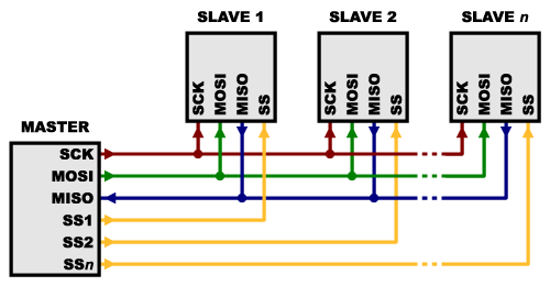
A synchronous serial interface always pairs its data line(s) with a
clock signal, so all devices on a synchronous serial bus share a common
clock. This makes for a more straightforward, often faster serial
transfer, but it also requires at least one extra wire between
communicating devices. Examples of synchronous interfaces include SPI,
and I2C.
Asynchronous means that data is transferred without support from an external clock signal.
This transmission method is perfect for minimizing the required wires
and I/O pins, but it does mean we need to put some extra effort into
reliably transferring and receiving data.
Rules of Serial
The asynchronous serial protocol has a number of built-in
rules - mechanisms that help ensure robust and error-free data
transfers. These mechanisms, which we get for eschewing the external
clock signal, are:
- Data bits,
- Synchronization bits,
- Parity bits,
- and Baud rate.
The protocol is highly
configurable. The critical part is making sure that both devices on a serial bus are configured to use the exact same protocols.
Baud Rate
The baud rate specifies how fast data is sent over a
serial line. It’s usually expressed in units of bits-per-second (bps).
If you invert the baud rate, you can find out just how long it takes to
transmit a single bit. This value determines how long the transmitter
holds a serial line high/low or at what period the receiving device
samples its line.
The only
requirement is that both devices operate at the same rate. One of the
more common baud rates, especially for simple stuff where speed isn’t
critical, is 9600 bps. Other “standard” baud are 1200, 2400, 4800, 19200, 38400, 57600, and 115200.
The higher a baud rate goes, the faster data is sent/received, but
there are limits to how fast data can be transferred. You usually won’t
see speeds exceeding 115200 - that’s fast for most micro-controllers. Get
too high, and you’ll begin to see errors on the receiving end, as
clocks and sampling periods just can’t keep up.
Framing the data
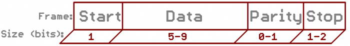
Each block (usually a byte) of data transmitted is actually sent in a packet or frame of bits. Frames are created by appending synchronization and parity bits to our data.
Data chunk
The real meat of every serial packet is the data it carries. We ambiguously call this block of data a chunk,
because its size isn’t specifically stated. The amount of data in each
packet can be set to anything from 5 to 9 bits. Certainly, the standard
data size is your basic 8-bit byte, but other sizes have their uses. A
7-bit data chunk can be more efficient than 8, especially if you’re just
transferring 7-bit ASCII characters.
After agreeing on a character-length, both serial devices also have to agree on the endianness
of their data. Is data sent most-significant bit (msb) to least, or
vice-versa? If it’s not otherwise stated, you can usually assume that
data is transferred least-significant bit (lsb) first.
Synchronization bits
The synchronization bits are two or three special bits transferred with each chunk of data. They are the start bit and the stop bit(s).
True to their name, these bits mark the beginning and end of a packet.
There’s always only one start bit, but the number of stop bits is
configurable to either one or two (though it’s commonly left at one).
The start bit is always indicated by an idle data line going from 1
to 0, while the stop bit(s) will transition back to the idle state by
holding the line at 1.
Parity bits
Parity is a form of very simple, low-level error checking. It comes
in two flavors: odd or even. To produce the parity bit, all 5-9 bits of
the data byte are added up, and the evenness of the sum decides whether
the bit is set or not.
For example, assuming parity is set to even and
was being added to a data byte like
0b01011101, which has an odd number of 1’s (5), the parity bit would be set to 1. Conversely, if the parity mode was set to odd, the parity bit would be 0.
Parity is optional, and not very widely used. It can be
helpful for transmitting across noisy mediums, but it’ll also slow down
your data transfer a bit and requires both sender and receiver to
implement error-handling (usually, received data that fails must be
re-sent).
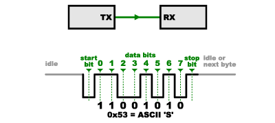
9600 8N1 (an example)
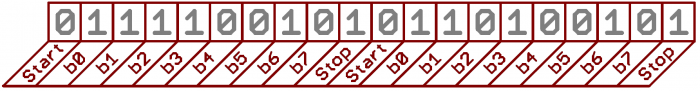
A device transmitting the ASCII characters ‘O’ and ‘K’ would have to create two packets of data. The ASCII value of O (that’s uppercase) is 79, which breaks down into an 8-bit binary value of
01001111, while K’s binary value is 01001011. All that’s left is appending sync bits.
It isn’t specifically stated, but it’s assumed that data is
transferred least-significant bit first. Notice how each of the two
bytes is sent as it reads from right-to-left.
Since we’re transferring at 9600 bps, the time spent holding each of those bits high or low is 1/(9600 bps) or 104 µs per bit.
For every byte of data transmitted, there are actually 10 bits being
sent: a start bit, 8 data bits, and a stop bit. So, at 9600 bps, we’re
actually sending 9600 bits per second or 960 (9600/10) bytes per second.
Wiring and Hardware
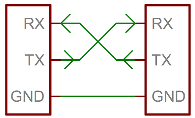
A serial bus consists of just two wires - one for sending
data and another for receiving. As such, serial devices should have two
serial pins: the receiver, RX, and the transmitter, TX.
case study
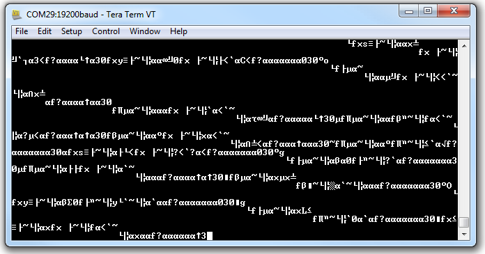
Baud Rate Mismatch
Baud rates are like the languages of serial communication. If two
devices aren’t speaking at the same speed, data can be either
misinterpreted, or completely missed. If all the receiving device sees
on its receive line is garbage, check to make sure the baud rates match
up.
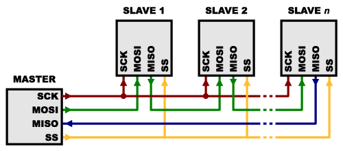
Bus Contention
Serial communication is designed to allow just two devices to
communicate across one serial bus. If more than one device is trying to
transmit on the same serial line you could run into bus-contention.
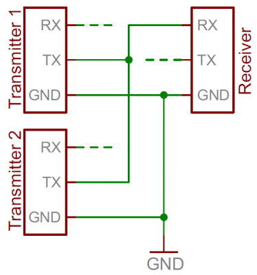
Two devices trying to transmit data at the same time, on the same line,
is bad! At “best” neither of the devices will get to send their data.
It can be safe to connect multiple receiving devices to a single transmitting device. Not really up to spec, but it’ll work.
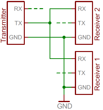
NOTE: In general - one serial bus, two serial devices!