Labels

Showing posts with label Protocols. Show all posts

Friday, 25 November 2016

Understanding of linux SPI driver Model

The kernel SPI subsystem is divided into Controller Driver and Protocol Drivers.

Controller Driver
A controller driver is represented by the structure spi_master. The driver for an SPI controller manages access to spi slave devices through a queue of spi_message transactions, copying data between CPU memory and an SPI slave device. For each such message it queues, it calls the message’s completion function when the transaction completes.
Protocol Driver
A Protocol driver is represented by the structure spi_driver, they pass messages through the controller driver to communicate with a Slave or Master device on the other side of an SPI link. 


Initializing and probing of SPI Controller Driver
For embedded System-on-Chip (SOC) based boards, SPI master controllers connect to their drivers using some non SPI bus, such as the platform bus. Initializing and probing SPI controller driver is performed using the platform bus. During the initial stage of platform driver registration stage of probe() in that code includes calling spi_alloc_master which allocated the structure spi_master in the kernel and during final stage calling spi_register_master() to hook up to this SPI bus glue.
SPI controller’s will usually be platform devices, and the controller may need some platform_data in order to operate properly. The “struct platform_device” will include resources like the physical address of the controller’s first register and its IRQ.
Platforms will often abstract the “register SPI controller” operation,maybe coupling it with code to initialize pin configurations in the board initialization files. This is because most SOCs have several SPI-capable controllers, and only the ones actually usable on a given board should normally be set up and registered.
1 /* spi bus : spi0 */
2 static struct platform_device mysoc_spi_dev0 = {
3 .name = “mysoc_spi”,
4 .id = 0,
5 . resource = &mysoc_spi_resources [0] ,
6 . num_resources = 2,
7 . dev = {
8 . platform_data = &mysoc_spi_dev0_data ,
9 },
10 };
11
21 static int __init mysoc_spi_init ( void )
22 {
23 …
24 platform_device_register (&mysoc_spi_dev0 );
25 …
28 }
29
 Listing 1: Registration of the SPI platform device with the platform bus.
On the driver’s side, the registration with the platform bus is achieved by populating a structure platform_driver and passing it to the macro module_platform_driver() as argument (Listing-2). The platform bus simply compares the driver.name member against the name of each device, as defined in the platform_device data structure (Listing 1); if they are the same the device matches the platform driver.
1 # define DRIVER_NAME “mysoc_spi”
2
3 static struct platform_driver mysoc_spi_driver = {
4 .probe = mysoc_spi_probe ,
5 .remove = mysoc_spi_remove,
6 .driver = {
7 .name = DRIVER_NAME ,
8 .owner = THIS_MODULE ,
9 .pm = &mysoc_spi_pm_ops ,
10 },
11 };
12 module_platform_driver ( mysoc_spi_driver );
Listing 2: Registration of the SPI platform driver with the platform bus.

 
As usual, binding a device to a driver involves calling the driver’s probe() function passing a pointer to the device as a parameter. The SPI controller driver registers with the SPI subsystem by using a structure spi_master that is instantiated and initialized by the SPI platform driver’s probe() function, as shown in Listing 3.
The sequence of operations performed on probing are the following:
  1. Get the device resource definitions.
  2. Allocate the appropriate memory and remap it to a virtual address for being accessed by the kernel.
  3. Load the device settings.
  4. Configure the device hardware.
  5. Register with the power management system.
  6. Create the per-device sysfs nodes.
  7. Request the interrupt and register the IRQ.
  8. Set up the struct spi_master and register the master controller driver with the SPI core.
On successful completion of above steps the driver is bounded to the devices representing the mysoc SPI controllers.

1 /* Probe function */
2 static int mysoc_spi_probe ( struct platform_device * pdev )
3 {
4 …
5 struct spi_master *master;
6 …
7 /* Allocate master */
8 master = spi_alloc_master(&pdev->dev, sizeof(struct spi_master));
9 …
10 /* Register with the SPI framework */
11 status = spi_register_master(master);
12 …
14 }

Listing 3: Registration of the SPI Controller Driver.

Wednesday, 19 October 2016

What is UART serial communication? how it is different from parallel communication?

Serial Communication

Before proceeding to further discussion on serial communication, let's take a brief intro for the parallel communication.

Parallel vs. Serial

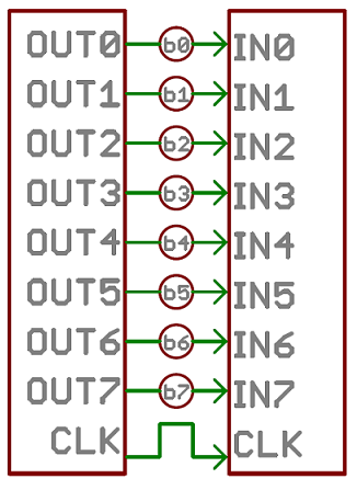
Parallel interfaces transfer multiple bits at the same time. They usually require buses of data - transmitting across eight, sixteen, or more wires. Data is transferred in huge, crashing waves of 1’s and 0’s.
Parallel Generalization 
An 8-bit data bus, controlled by a clock, transmitting a byte every clock pulse. 9 wires are used.
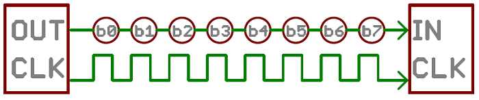
Serial interfaces stream their data, one single bit at a time. These interfaces can operate on as little as one wire, usually never more than four.
Serial Generalization 
 Parallel communication certainly has its benefits. It’s fast, straightforward, and relatively easy to implement. But it requires many more input/output (I/O) lines.you know that the I/O lines on a microprocessor can be precious and few. So, we often opt for serial communication, sacrificing potential speed for pin real estate.

Asynchronous Serial

Over the years, dozens of serial protocols have been crafted to meet particular needs of embedded systems. USB (universal serial bus), and Ethernet, are a couple of the more well-known computing serial interfaces. Other very common serial interfaces include SPI, I2C, and the serial standard we’re here to talk about today. Each of these serial interfaces can be sorted into one of two groups: synchronous or asynchronous.
A synchronous serial interface always pairs its data line(s) with a clock signal, so all devices on a synchronous serial bus share a common clock. This makes for a more straightforward, often faster serial transfer, but it also requires at least one extra wire between communicating devices. Examples of synchronous interfaces include SPI, and I2C.
Asynchronous means that data is transferred without support from an external clock signal. This transmission method is perfect for minimizing the required wires and I/O pins, but it does mean we need to put some extra effort into reliably transferring and receiving data.

Rules of Serial

The asynchronous serial protocol has a number of built-in rules - mechanisms that help ensure robust and error-free data transfers. These mechanisms, which we get for eschewing the external clock signal, are:
  • Data bits,
  • Synchronization bits,
  • Parity bits,
  • and Baud rate.
The protocol is highly configurable. The critical part is making sure that both devices on a serial bus are configured to use the exact same protocols.

Baud Rate

The baud rate specifies how fast data is sent over a serial line. It’s usually expressed in units of bits-per-second (bps). If you invert the baud rate, you can find out just how long it takes to transmit a single bit. This value determines how long the transmitter holds a serial line high/low or at what period the receiving device samples its line.
The only requirement is that both devices operate at the same rate. One of the more common baud rates, especially for simple stuff where speed isn’t critical, is 9600 bps. Other “standard” baud are 1200, 2400, 4800, 19200, 38400, 57600, and 115200.
The higher a baud rate goes, the faster data is sent/received, but there are limits to how fast data can be transferred. You usually won’t see speeds exceeding 115200 - that’s fast for most micro-controllers. Get too high, and you’ll begin to see errors on the receiving end, as clocks and sampling periods just can’t keep up.

Framing the data

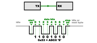
Each block (usually a byte) of data transmitted is actually sent in a packet or frame of bits. Frames are created by appending synchronization and parity bits to our data.
Serial Packet 

Data chunk

The real meat of every serial packet is the data it carries. We ambiguously call this block of data a chunk, because its size isn’t specifically stated. The amount of data in each packet can be set to anything from 5 to 9 bits. Certainly, the standard data size is your basic 8-bit byte, but other sizes have their uses. A 7-bit data chunk can be more efficient than 8, especially if you’re just transferring 7-bit ASCII characters.
After agreeing on a character-length, both serial devices also have to agree on the endianness of their data. Is data sent most-significant bit (msb) to least, or vice-versa? If it’s not otherwise stated, you can usually assume that data is transferred least-significant bit (lsb) first.

Synchronization bits

The synchronization bits are two or three special bits transferred with each chunk of data. They are the start bit and the stop bit(s). True to their name, these bits mark the beginning and end of a packet. There’s always only one start bit, but the number of stop bits is configurable to either one or two (though it’s commonly left at one).
The start bit is always indicated by an idle data line going from 1 to 0, while the stop bit(s) will transition back to the idle state by holding the line at 1.

Parity bits

Parity is a form of very simple, low-level error checking. It comes in two flavors: odd or even. To produce the parity bit, all 5-9 bits of the data byte are added up, and the evenness of the sum decides whether the bit is set or not. 

For example, assuming parity is set to even and was being added to a data byte like 0b01011101, which has an odd number of 1’s (5), the parity bit would be set to 1. Conversely, if the parity mode was set to odd, the parity bit would be 0.

Parity is optional, and not very widely used. It can be helpful for transmitting across noisy mediums, but it’ll also slow down your data transfer a bit and requires both sender and receiver to implement error-handling (usually, received data that fails must be re-sent).

9600 8N1 (an example)

A device transmitting the ASCII characters ‘O’ and ‘K’ would have to create two packets of data. The ASCII value of O (that’s uppercase) is 79, which breaks down into an 8-bit binary value of 01001111, while K’s binary value is 01001011. All that’s left is appending sync bits.
It isn’t specifically stated, but it’s assumed that data is transferred least-significant bit first. Notice how each of the two bytes is sent as it reads from right-to-left.
"OK" Packet
Since we’re transferring at 9600 bps, the time spent holding each of those bits high or low is 1/(9600 bps) or 104 µs per bit.

For every byte of data transmitted, there are actually 10 bits being sent: a start bit, 8 data bits, and a stop bit. So, at 9600 bps, we’re actually sending 9600 bits per second or 960 (9600/10) bytes per second.

Wiring and Hardware

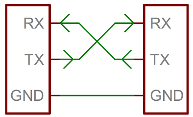
A serial bus consists of just two wires - one for sending data and another for receiving. As such, serial devices should have two serial pins: the receiver, RX, and the transmitter, TX.
Serial Wiring

case study 

Baud Rate Mismatch

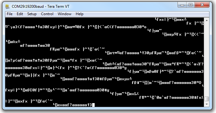
Baud rates are like the languages of serial communication. If two devices aren’t speaking at the same speed, data can be either misinterpreted, or completely missed. If all the receiving device sees on its receive line is garbage, check to make sure the baud rates match up.

Baud Mismatch


Bus Contention

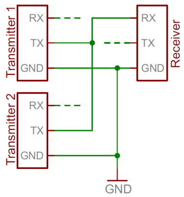
Serial communication is designed to allow just two devices to communicate across one serial bus. If more than one device is trying to transmit on the same serial line you could run into bus-contention.
Bus contention example 
 Two devices trying to transmit data at the same time, on the same line, is bad! At “best” neither of the devices will get to send their data.

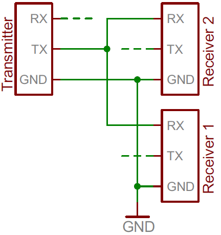
It can be safe to connect multiple receiving devices to a single transmitting device. Not really up to spec, but it’ll work.
Safe but iffy implementation of one transmitter/two receivers 
 
 NOTE: In general - one serial bus, two serial devices!
 

Wednesday, 12 October 2016

what is spi and how it is different from serial commmunication?

Serial Peripheral Interface (SPI)

The Serial Peripheral Interface (SPI) bus is a synchronous serial communication interface specification used for short distance communication, primarily in embedded systems.

Before going further in to the discussion on the SPI, let's take a look at Asynchronous serial interface and its drawbacks.

  • Asynchronous means that data is transferred without support from an external clock signal. This transmission method is perfect for minimizing the required wires and I/O pins, but it does mean we need to put some extra effort into reliably transferring and receiving data.
  • A common serial port, the kind with TX and RX lines, is called “asynchronous” (not synchronous) because there is no control over when data is sent or any guarantee that both sides are running at precisely the same rate.
To work around this problem, asynchronous serial connections add extra start and stop bits to each byte help the receiver sync up to data as it arrives. Both sides must also agree on the transmission speed (such as 9600 bits per second) in advance. Slight differences in the transmission rate aren’t a problem because the receiver re-syncs at the start of each byte.
Asynchronous serial waveform 
Asynchronous serial works just fine, but has a lot of overhead in both the extra start and stop bits sent with every byte, and the complex hardware required to send and receive data. And as you’ve probably noticed in your own projects, if both sides aren’t set to the same speed, the received data will be garbage. This is because the receiver is sampling the bits at very specific times.

For more detailed discussion on serial communication please see Serial Communication

SPI

SPI is a “synchronous” data bus, which means that it uses separate lines for data and a “clock” that keeps both sides in perfect sync. The clock is an oscillating signal that tells the receiver exactly when to sample the bits on the data line. This could be the rising (low to high) or falling (high to low) edge of the clock signal; the datasheet will specify which one to use. When the receiver detects that edge, it will immediately look at the data line to read the next bit

  • The SPI bus can operate with a single master device and with one or more slave devices.
  • If a single slave device is used, the SS pin may be fixed to logic low if the slave permits it. Some slaves require a falling edge of the chip select signal to initiate an action.

Data transmission

To begin communication, the bus master configures the clock, using a frequency supported by the slave device, typically up to a few MHz. The master then selects the slave device with a logic level 0 on the select line.

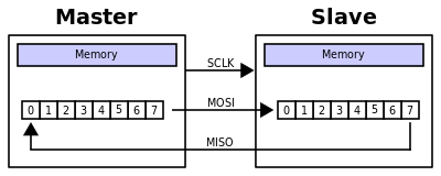
During each SPI clock cycle, a full duplex data transmission occurs. The master sends a bit on the MOSI line and the slave reads it, while the slave sends a bit on the MISO line and the master reads it. This sequence is maintained even when only one-directional data transfer is intended.
  • Transmissions normally involve two shift registers of some given word size, such as eight bits, one in the master and one in the slave; they are connected in a virtual ring topology. 
  • Data is usually shifted out with the most-significant bit first, while shifting a new least-significant bit into the same register. At the same time, Data from the counterpart is shifted into the least-significant bit register. 
  • After the register bits have been shifted out and in, the master and slave have exchanged register values. If more data needs to be exchanged, the shift registers are reloaded and the process repeats. 
  •  Transmission may continue for any number of clock cycles. When complete, the master stops toggling the clock signal, and typically deselects the slave.

Clock polarity and clock phase

  • At CPOL=0 the base value of the clock is zero, i.e. the idle state is 0 and active state is 1.
    • For CPHA=0, data are captured on the clock's rising edge (low→high transition) and data is output on a falling edge (high→low clock transition).
    • For CPHA=1, data are captured on the clock's falling edge and data is output on a rising edge.
  • At CPOL=1 the base value of the clock is one (inversion of CPOL=0), i.e. the idle state is 1 and active state is 0.
    • For CPHA=0, data are captured on clock's falling edge and data is output on a rising edge.
    • For CPHA=1, data are captured on clock's rising edge and data is output on a falling edge.


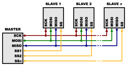
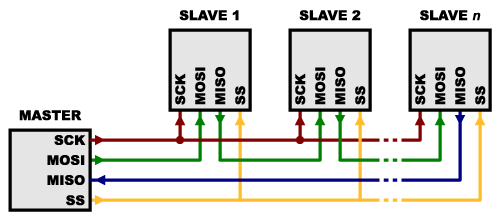
Multiple slaves

There are two ways of connecting multiple slaves to an SPI bus:
  • In general, each slave will need a separate SS line. To talk to a particular slave, you’ll make that slave’s SS line low and keep the rest of them high (you don’t want two slaves activated at the same time, or they may both try to talk on the same MISO line resulting in garbled data). Lots of slaves will require lots of SS lines;
alt text

  •  On the other hand, some parts prefer to be daisy-chained together, with the MISO (output) of one going to the MOSI (input) of the next. In this case, a single SS line goes to all the slaves. Once all the data is sent, the SS line is raised, which causes all the chips to be activated simultaneously. This is often used for daisy-chained shift registers and addressable LED drivers.
alt text 
Note that, for this layout, data overflows from one slave to the next, so to send data to any one slave, you’ll need to transmit enough data to reach all of them. Also, keep in mind that the first piece of data you transmit will end up in the last slave.

Advantages of SPI:

  • It’s faster than asynchronous serial
  • The receive hardware can be a simple shift register
  • It supports multiple slaves

Disadvantages of SPI:

  • It requires more signal lines (wires) than other communications methods
  • The communications must be well-defined in advance (you can’t send random amounts of data whenever you want)
  • The master must control all communications (slaves can’t talk directly to each other)
  • It usually requires separate SS lines to each slave, which can be problematic if numerous slaves are needed.
 Bibliography:

Tuesday, 11 August 2015

what is RTP, RTSP and RTCP?

RTP (Real Time Protocol)
Real-Time Protocol (RTP) is a transport protocol that was developed for streaming data. RTP includes extra data fields not present in TCP. It provides a timestamp andsequence number to facilitate the data transport timing, and allows control of the media server so that the video stream is served at the correct rate for real-time display. The media player then uses these RTP fields to assemble the received packets into the correct order and playback rate.
  • Sequence number
    The value of this 16-bit number increments by one for each packet. It is used by the player to detect packet loss and then to sequence the packets in the correct order. The initial number for a stream session is chosen at random.
  • Timestamp
    This is a sampling instance derived from a reference clock to allow for synchronization and jitter calculations. It is monotonic and linear in time.
  • Source identfiers
    CSRC is a unique identifier for the synchronization of the RTP stream. One or more CSRCs exist when the RTP stream is carrying information for multiple media sources. This could be the case for a video mix between two sources or for embedded content.
In a sense, RTP is not a true transport protocol, and it is designed to use UDP as a packet transport mechanism. In other words, RTP usually runs on UDP, and uses its multiplexing and checksum features. Note that RTP does not provide any control of the quality of service or reservation of network resources.

rtp_header.png 


RTCP (Real Time Control Protocol)
RTCP is used in conjunction with RTP. In other words, whenever an RTP connection is made, an RTCP connection also needs to be made. This connection is made using a second neighboring UDP port; if the RTP connection uses port 1500, then the RTCP connection uses port 1501.
RTCP gives feedback to each participant in an RTP session that can be used to control the session. The messages includes reception reports, including number of packets lost and jitter statistics (early or late arrivals). This information potentially can be used by higher layer applications to modify the transmission. For example, the bit rate of a stream could be changed to counter network congestion. Some RTCP messages relate to control of a video conference with multiple participants.
RTCP provides the following features:
  • Allow synchronization between different media types, such as video and audio. It has timestamp that is used by the receiver to align the clocks in each different RTP stream so that video and audio signals can be synced.
  • Report reception quality to the senders.
  • Provide identification of the senders in the RTP session so that new receivers can join and figure out which streams they need to obtain in order to participate fully.


Session Description Protocol (SDP)
SDP is a media description format intended for describing multimedia sessions, including video-conferencing. It includes session announcement and session invitation. Below is a sample of SDP.
v=0
o=- 32176 32176 IN IP4 13.16.32.209
s=ONetworkRenderer
i=OLiveBroadcast
c=IN IP4 221.1.0.1
t=0 0
b=AS:32
a=x-qt-text-nam:ONetwork Renderer
a=x-qt-text-inf:OLive Broadcast
a=x-qt-text-cmt:source application:ONetwork Renderer
a=x-qt-text-aut:
a=x-qt-text-cpy:
a=range:npt=0-
m=audio 22002 RTP/AVP 96
a=rtpmap:96 MP4A-LATM/44100/1
a=fmtp:96 cpresent=0;config=400024100000
a=control:trackID=1
The description of the sdp is shown below:
v: Version
o: Originator, session identifier, version, network type, protocol type, address
s: Subject
i: Information
c: Connection type, address
t: Start and stop times
m: Media type, port number, transport protocol, RTP profile
a: Dynamic payload type description
When we changed something in the sdp, the client should start a new session to see the effect of the changes. It works the same way as the html file. The web server holds the new html pages, and a client needs to refresh the the page to see any changes made.


RTSP (Real Time Streaming Protocol)
RTSP provides a means for users to control media sessions. RTSP does not actually provide for the transport of video signals but it allows these signals to be controlled by a user. The RTSP (Real Time Streaming Protocol) is a network control protocol to control streaming media servers. The protocol is used for establishing and controlling media sessions between the the streaming server and client. RTSP is considered more of a framework than a protocol. RTSP is designed to work on top ofRTP to both control and deliver real-time content.

streaming_link.png 

rtsp 
RTSP is one of the number of different protocols have been developed to facilitate real-time streaming of multimedia content. Streaming means that the mean frame rate of the video viewed at the player is dictated by the transmitted frame rate. The delivery rate has to be controlled so that the video data arrives just before it is required for display on the player. The associated audio track or tracks must also remain synchronized to the video. IP data transmission is not a synchronous process and delivery is by best effort. To achieve synchronism, timing references have to be embedded in the stream.

rtsp_tcp.png 
It delivers content as a unicast stream. It is an application-level protocol that was created specifically to control the delivery of real-time data, such as audio and video content. It is implemented over a correction-oriented transport protocol. It supports player control actions such as stopping, pausing, rewinding, and fast-forwarding.
If the connection URL uses RTSP, RTSP automatically negotiates the best delivery mechanism for the content. It then directs the RTP protocol to deliver streaming content using UDP, or using a TCP-based protocol on a network that does not support UDP.
The default transport layer port number is 554. 
streaming_control.png 
  • OPTIONS
    An OPTIONS request returns the request types the server will accept.
  • DESCRIBE
    A DESCRIBE request includes an RTSP URL (rtsp://...), and the type of reply data that can be handled. The default port for the RTSP protocol is 554 for both UDP and TCP transports. This reply includes the presentation description, typically inSession Description Protocol (SDP) format. Among other things, the presentation description lists the media streams controlled with the aggregate URL. In the typical case, there is one media stream each for audio and video.
  • SETUP
    A SETUP request specifies how a single media stream must be transported. This must be done before a PLAY request is sent. The request contains the media stream URL and a transport specifier. This specifier typically includes a local port for receiving RTP data (audio or video), and another for RTCP data (meta information). The server reply usually confirms the chosen parameters, and fills in the missing parts, such as the server's chosen ports. Each media stream must be configured using SETUP before an aggregate play request may be sent.
  • PLAY
    A PLAY request will cause one or all media streams to be played. Play requests can be stacked by sending multiple PLAY requests. The URL may be the aggregate URL (to play all media streams), or a single media stream URL (to play only that stream). A range can be specified. If no range is specified, the stream is played from the beginning and plays to the end, or, if the stream is paused, it is resumed at the point it was paused.
  • PAUSE
    A PAUSE request temporarily halts one or all media streams, so it can later be resumed with a PLAY request. The request contains an aggregate or media stream URL. A range parameter on a PAUSE request specifies when to pause. When the range parameter is omitted, the pause occurs immediately and indefinitely.
  • RECORD
    The RECORD request can be used to send a stream to the server for storage.
  • TEARDOWN
    A TEARDOWN request is used to terminate the session. It stops all media streams and frees all session related data on the server.
A streaming server works with the client to send audio and/or video over the Internet or Intranet and play it almost immediately. They allow real-time 'broadcasting' of live events, and the ability to control the play-back of on-demand content. Playback begins as soon as sufficient data has downloaded. The viewer can skip to a point part way through a clip without needing to download the beginning. If the data can not be downloaded fast enough, a streamed web cast sacrifices quality in order for the viewing to remain synchronised with the original timing of the content.
With Windows Media Server, RTSP supports the following features:
  • RTP packets can stream over UDP or over TCP. If the client can tolerate packet loss, streaming over UDP can be more efficient than TCP because UDP does not incur the overhead of retransmitting lost packets.
  • The encapsulation of Advanced Streaming Format (ASF) packets in RTP is proprietary.
  • The description of the ASF file, called ASF encapsulated in SDP, is proprietary.
  • WMS supports retransmission of lost RTP packets sent over UDP. This behavior allows a client to give up on expired RTP packets, which in turn helps the client avoid falling behind after losing packets.
  • WMS supports a forward error correction (FEC) scheme for RTP packets.
  • Streaming with RTSP fails if a firewall separates the client and server, and the firewall blocks the ports and protocols that RTSP uses. This problem is especially common with home Internet gateways. Even if the gateway has a built-in RTSP NAT, streaming might fail at times.
  • RTSP has the overhead of requiring multiple requests before playback can begin. However, the client can pipeline many of these requests and send them over a single TCP connection, in which case WMP does not need to block waiting for a response.

rtsp_rfc.png

what is live streaming and on demand streaming?

live_vs_ondemand.png


One of the primary reasons that producers use streaming servers is because once video is stored (or cached) on a hard drive, it's very easy to copy. Streaming video can be cache-less, which makes it inherently more secure.
Most Internet Video is delivered by progressive download. For example, YouTube video is delivered by progressive download.
What's happening when we watch a movie from a web site? First, the video file is placed on a server. Second, we click a link to that file on a web page. The server sends the data to us. It may appear to be streaming since playback can begin almost immediately. The progressive download feature in most media players allows them to begin playing the file as soon as enough data has been downloaded.
Years ago, the only acceptable way to deliver video was via streaming protocols such as RTSP, RTP, or RTCP that required proprietary players and expensive servers. Often referred to as Streaming Video, these solutions were costly and did not scale well but offered more functionality at the time. Yet, as technology has evolved, there was a wholesale migration towards to a new way of delivering video delivery via the standard HTTP protocol (often referred to as Progressive Download). Less expensive, it also scales well. This shift has occurred due to customer acceptance once the technology evolved to include many of the features that were once only possible with streaming protocols.
By using metadata attached to encoded files, progressive download can now allow users full seek and navigation at any time without requiring full file download. By using bandwidth throttling (specify bit rate that files should be delivered at), it is now possible to deliver only the amount of video that will be viewed, preventing wasted bandwidth. 
To maximize security, no-cache headers can be used to prevent browsers from storing content in cache and further DRM protection is easily available from partners.
So, with the broader availability of high-bandwidth networks and new media delivery features of web server, the differences that previously favored the use of a stream server over a web server for delivering digital media content have blurred. In non-multicast streaming scenarios, depending upon your business need, a stream server or a web server can both be viable options for digital media content delivery today.
However, in many ways it is inferior to adaptive streaming - Http Live Streaming (HLS) which will be described later.

download_and_play_vs_streaming.png 


Progressive download can be achieved using a regular web (http) server. The client (player) handles the buffering and playing during the download process.
The quality of the file from the progressive download is pre-determined. A user watching from a mobile connection on a 3 inch screen will have the same video as a user watching from a cable modem connection on a 1080p TV. The player is unable to dynamically adjust based on the user's network and screen conditions. Furthermore, if a user starts in a high-bandwidth environment, then moves to a low-bandwidth environment, HTTP Progressive Download is completely unable to keep pace. HLS, however, handles this scenario gracefully with minimal rebuffering and lag.

 web_server_vs_streaming_server.png

what is streaming? how it is different from downloading?

Video Streaming - Terminology
  • Encode
    To convert raw audio and/or video content into compressed form using technologies such as MPEG.
  • Transcode
    To convert a video signal that is encoded in one technology (MPEG-2) into another (MPEG-4).
  • Transrate
    To change the bit rate of compressed video stream.
  • Transmux
    To convert to a different container format without changing the file contents.
  • Pull
    A Pull is a connection initiated by a streaming server to receive a broadcast from a designated encoder for re-distribution across a network.
  • Push
    A Push is a connection initiated by an encoder to a streaming server to receive a broadcast for re-distribution across a network. This requires a username and password.
  • Latency
    Latency refers to the amount of time taken for data to complete a return trip between two points.
  • ABR
    Adaptive BitRate Video Streaming, the protocol developed by apple and used for iOS (and many products)
  • RTMP
    Real Time Media Protocol, developed by Adobe used by Flash
  • CBR (Constant Bit Rate) encoding
    The encoding software attempt to keep the total bits/second constant through the entire video. This makes the size of the file predictable and easier to stream. Most modern CODECs will allow you to set an upper threshold on the bit rate and allow the rate to drop when it is not required for quality to help reduce the amount of bandwidth used.
  • Variable bit rate encoding (VBR)
    A method of encoding video that first analyses the video and then compresses it. While it can take up to twice as long to encode the video, they are compressed at an optimal rate for the smallest file size. The variability in the data rate of the data stream does not make it appropriate for RTSP streamed content, but good for progressive download or video on CDs or other physical media.